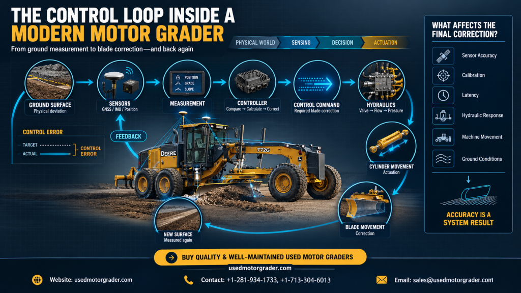
A grader crosses a stretch of subgrade that sits a few millimeters high on one side. Yet before the blade responds, a receiver has to fix a position, an inertial sensor has to report an angle, a controller has to compare both against a design, a valve has to open, oil has to flow, a cylinder has to swing a heavy moldboard, and the material under the edge has to yield. Then the machine measures the result and starts over.
Automated grading does not rest on one clever sensor or one fast computer. It rests on the complete loop, and the loop is only as good as its slowest, noisiest, or loosest link. Public documentation mostly describes components one at a time, so this article follows a single correction from ground to blade and back, asking at each stage what happens, what information or force is involved, where error or delay can enter, and how that reaches the finished surface.
The Loop in One View
Grader systems differ by brand, model, and option package, and nothing below describes every machine. The pattern, though, is a closed loop, laid out in this table.
The Complete Control Loop
| Stage | What Happens | Main Signal | Typical Error Source | Why It Matters |
| Ground and blade state | Surface and blade sit off target | Elevation, cross slope, pitch, roll | Ruts, uneven material depth | Defines what must be corrected |
| Sensing | Sensors report position and angles | GNSS fix, IMU rates, cylinder extension | Noise, multipath, drift, mounting error | Bad input taints every later stage |
| Processing | Signals filtered and fused | Estimated blade position | Filter lag, calibration offsets | Smoothing removes noise but adds delay |
| Controller | Measured position compared with design | Control error | Model errors, gain choice | Sets how hard the system corrects |
| Hydraulic command | Electrical command drives a valve | Valve current or network message | Deadband, hysteresis | Small commands may move no oil |
| Cylinder and blade | Oil extends a cylinder, linkage moves the edge | Flow, pressure, extension | Load, oil temperature, linkage play | Cylinder motion is not edge motion |
| Ground response | Edge cuts or spreads material | Cutting force, new surface | Material type, wheel slip, speed | The changed surface is measured again |
What the Machine Actually Senses
The machine never sees a finished grade the way an operator does. It receives measurements and infers the blade’s relationship to a target surface. What it is really controlling is physical: elevation, cross slope, and longitudinal grade, disturbed by ruts, uneven material depth, wheel tracks, and frame pitch and roll. Even the windrow ahead of the edge changes what the next measurement finds.
Sensor layouts vary. Cat describes Cross Slope Assist as using the drawbar, circle, and moldboard center shift to hold the moldboard on grade, managing one blade end while the operator handles the other. Its 3D option adds two GNSS receivers that Caterpillar says are built in and calibrated at the factory. That variation is why the exact configuration of any CAT motor grader for sale matters more than a feature label.
Deere took a different route. It says SmartGrade combines GNSS, an IMU, and in-cylinder position sensing, where a magnet on a rod inside each cylinder returns a pulse whose timing reveals extension. Deere claims blade position within a millimeter. For buyers weighing John Deere motor graders for sale, that puts the cylinders themselves inside the measurement chain.
Other machines lean on outside suppliers. Volvo says its joystick-equipped G900C graders accept Topcon, Trimble, or Leica blade control plug-and-play, and Komatsu’s GD655-7 launch material describes Topcon 3D-MC support with no aftermarket valve. Simpler setups follow a physical reference: Topcon’s sonic tracker times echoes from a curb, stringline, or existing surface, with a temperature bail compensating for rapid air temperature changes.
This overview of how sensor technology is transforming the modern grader covers the trend, and the fastest update figures below come from dozer systems, a reminder of how motor grader innovation compares with other heavy equipment.
Sensor and Measurement Technologies
| Technology | Primary Measurement | Main Role | Key Limitation | Effect on Control Loop |
| GNSS with RTK | Antenna position | Places machine against design | Multipath, obstructions, lost corrections | Slow position needs faster help |
| IMU | Angular rate, acceleration | Fast pitch, roll and blade motion | Drift accumulates | Fills gaps between GNSS fixes |
| Slope sensor | Blade cross slope | Holds slope | Damping adds delay | Slope error during quick height changes |
| Cylinder position | Rod extension | Blade geometry, feed-forward | Measures cylinder, not edge | Linkage wear stays invisible |
| Sonic tracker | Distance to a physical reference | Two-dimensional following | Air temperature, reference quality | Only as good as the reference |
Measurement Is Not the Same as Truth
A sensor output is an estimate, not a fact. Trimble’s MS995 sheet lists RTK accuracy of 8 mm plus 0.5 ppm horizontal and 15 mm plus 0.5 ppm vertical, then warns that multipath, obstructions, satellite geometry, and atmospheric conditions can degrade it. That figure describes an antenna under stated conditions, not a cutting edge on a vibrating frame that pitches, rolls, and articulates below it.
Inertial sensors have their own flaw. GNSS and inertial engineers note that every IMU drifts and errors accumulate, so systems typically blend inertial data with GNSS updates through a Kalman-type filter. A Topcon dozer patent describes three accelerometers and three rate gyros feeding blade elevation, velocity, and slope estimates. Grader makers do not publish their exact fusion algorithms, so this report describes the engineering function, not proprietary code. Add vibration, misaligned mounts, dropouts, and the distance traveled between measurement and action, and raw signals need filtering before a controller can trust them.
From Raw Signal to Control Decision
After acquisition, signals are conditioned, filtered, and fused, then placed in a common coordinate frame so the edge can be located relative to the design. The controller subtracts measured position from desired position. That difference, the control error, drives everything after it.
How error becomes a request rests on standard control ideas: gain (how hard the response is per unit of error), deadband (a zone of error deliberately ignored), and damping (resistance to overshoot). A Topcon patent describes proportional-derivative control for blade slope and simple proportional control for side shift. That is one documented embodiment, not proof that every grader runs a textbook PID controller. Trimble’s dozer software lets operators adjust machine response to material conditions, which shows response is a setting, not a constant.
The controller also weighs machine speed, orientation, articulation, hydraulic limits, and sensor health. That logic is proprietary, and its quality is part of what separates the invisible electronics and software inside motor graders from one brand to the next.
From Command to Hydraulic Motion
A correction leaves the controller as an electrical command to a proportional valve, which positions a spool roughly in proportion to the command signal. Danfoss’s PVG 32 documentation, a common mobile hydraulics reference, describes spool deadband, hysteresis measured at stated voltage and frequency, and typical results given under stated conditions such as oil viscosity and temperature. It also explains that compensated spools keep flow proportional to spool opening regardless of load. From an engineering perspective, pump capacity and pressure still cap cylinder speed. Komatsu’s blade-lift accumulators, which absorb impacts, are a reminder that circuits contain compliance.
A small command can fall inside deadband and move nothing, then a larger one moves the blade abruptly. Cold or aged oil, worn seals, and internal leakage change the behavior further. A road grader for sale that has spent years in heavy work may carry hydraulic habits its sensors never report.
The Blade Does Not Move in Isolation
Cylinder extension is not edge movement. Lift, tilt, side shift, circle rotation, drawbar position, articulation, front-wheel lean, and frame pitch and roll all combine in the cutting edge’s final position. A 2025 engineering study of grader earthmoving mechanisms treats them as interconnected hydraulic actuators and uses kinematic analysis, the geometry of how linkages turn cylinder travel into edge travel, to determine blade pose.
A Caterpillar Trimble patent makes the same point: how far a second lift cylinder must move depends on cylinder and linkage geometry, so it follows the first to hold cross slope during quick height changes. On John Deere motor graders for sale with SmartGrade, dealer RDO says accuracy holds while the operator leans the wheels, articulates and pitches the blade, which implies the system tracks each of those angles. Change one geometry and another shifts.
The Ground Fights Back
Real material does not respond like a simulation. Wet clay sticks and smears, loose aggregate flows and windrows, dry compacted or frozen ground resists penetration and deflects the edge, and soft shoulders give way under the wheels. Blade loading pulls on engine power and traction, so wheel slip or a surging machine changes how steadily the edge travels. How tandem-drive power reaches the wheels therefore shapes how consistent a pass can be.
These effects are engineering reasoning, not published test data, but manufacturers design around them. Cat’s Stable Blade detects blade bounce and dampens it, and Equipment World reports it can slow the new 140 when bounce would hurt grade. Trimble’s GradeMax lets dozer operators tune response for soil conditions. Identical commands make different surfaces in different materials.
Latency: The Invisible Variable
Delay enters at every handoff:
- Measurement latency: time to sense and update a position or angle.
- Communication latency: time for data to cross modules and networks.
- Computational latency: filtering, fusion, and control calculation.
- Actuation latency: from command to meaningful oil flow.
- Mechanical latency: from cylinder motion to real edge movement, including play.
- Ground-response latency: from edge movement to a measurably different surface.
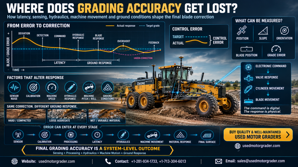
Published figures are thin. Topcon says a conventional single-sensor GNSS system processes location about 10 times a second, while its dual-IMU dozer system processes up to 100. Exact end-to-end latency is system-specific and generally undisclosed. A Caterpillar Trimble patent documents one case, explaining that inclinometers are damped to suppress vibration noise, and that damping delays the output, so quick blade height changes produce an erroneous cross slope before the sensor reports anything. A Topcon patent adds that hydraulic delay under proportional control can cause blade instability and wave-like patterns in the finished ground.
Sensor Accuracy Is Not System Accuracy
An accurate sensor does not guarantee an accurate surface. Deere’s within-a-millimeter claim describes cylinder sensing and Trimble’s RTK figures describe an antenna. Neither describes the finished grade, which also depends on calibration, machine geometry, controller processing, hydraulic response, blade wear, operator input, material, target model quality and positioning quality. A motor grader for sale that lists grade control tells a buyer which parts exist, not how well the whole chain performs. Blade wear matters directly: uneven moldboard wear can reveal how a machine has been worked, and a worn edge is no longer the geometry the calibration assumed.
Speed Changes the Math
Speed sets how much ground passes between measurements. As simple arithmetic, not a machine specification, a grader at 8 km/h covers about 22 cm between fixes at 10 updates per second. Faster travel leaves less distance for a delayed correction to finish. Slower travel gives it more, but material flow, traction and pass strategy change too, so speed is a trade-off, not a rule.
Overshoot, Undershoot and Hunting
Suppose the system finds the blade low and commands it up. Hydraulic and mechanical delay mean the edge keeps rising after the measured error has shrunk to zero. The blade overshoots, the controller commands it down, and the same delay overshoots again. That repeating swing is hunting, and it leaves the wave-like pattern the Topcon patent describes. Too little response causes the opposite: undershoot and a blade that seems lazy. Aggressive gain, noisy measurements, high speed, inertia, and poor calibration all push a system toward one extreme or the other.
One Correction, Start to Finish
The edge meets a low spot. Sensors report the change, the controller subtracts measured from desired grade, and the error becomes a raise command. A valve opens, oil moves a cylinder, and linkage lifts the edge. The edge spreads material into the hollow, the surface changes, sensors measure again, and the controller judges what error remains. If some remains, the cycle repeats until the error falls inside the system’s tolerance.
Accuracy leaks out in three places: before the command (sensor, calibration, reference and model errors), during it (processing, communication and hydraulic response), and after it (linkage, kinematics, material and the changing surface).
Where Control Accuracy Can Be Lost
| Control-Loop Factor | Typical Problem | Physical or Technical Consequence | Potential Mitigation |
| Sensor noise | Vibration, multipath jitter | Blade chases false error | Filtering, fusion, isolation |
| Calibration error | Offset in mounting or geometry | Constant grade bias | Recalibrate after repairs |
| Signal loss | RTK corrections drop | Position degrades | Base placement, IMU bridging |
| Latency | Filter, network, hydraulic delay | Late correction, hunting | Feed-forward, damping, lower speed |
| Hydraulic response | Deadband, hysteresis, cold or worn oil | Blade ignores small commands, then jumps | Warm-up, fluid, valve service |
| Mechanical wear | Play in circle, pins, bushings, edge | Cylinder motion misses the edge | Inspect, recalibrate |
| Ground variability | Soft, wet or loose material | Response differs per pass | Adjust response and pass strategy |
Automation and the Operator
Automated correction is not autonomy. Cat’s guide says its systems strengthen operator skill rather than replace it, and the operator still chooses speed, setup, calibration, target model, and how aggressively to work the material, then steps in when conditions exceed the system’s assumptions. Software can recompute error continuously in ways no person could sustain, but it cannot judge a soft spot. Crews moving between used motor graders of different generations also meet different behaviors, and features that demand constant adjustment can cost more attention than they save. The debate over hardware versus workflow applies here: strong hardware still depends on how the crew uses it.
The Real Control Loop
The real loop is not sensor to computer to blade. It runs from ground condition through sensing, measurement, interpretation, error calculation, control decision, command transmission, hydraulic response, mechanical response, and material interaction to a changed surface and a new measurement. Every link influences the next, which is why final grade accuracy is a system-level outcome, not a component specification.
What This Means for Used Equipment Buyers
When evaluating used motor graders, the loop suggests asking about the whole chain instead of counting features:
- Sensors, GNSS receivers, radios, and cylinder position sensors: condition and mounting.
- Display, controller, wiring, and connectors: intermittent faults and corrosion.
- Calibration history, especially after blade, circle, or cylinder work.
- Hydraulic behavior: smooth, proportional movement without drift or lurching.
- Blade and circle wear, which changes geometry.
- Software versions and upgrade paths, since software update cycles increasingly separate a machine that keeps improving from one that stalls.
- Documentation for retrofit systems and who installed them.
Cat says its factory sensor preparation makes adding 2D or 3D control faster and more cost-effective later, so a CAT motor grader for sale with that groundwork can shorten an upgrade.
Advanced hardware does not ensure consistent results if the loop is compromised, and a plain machine is not automatically poor. A used motor grader for sale is best judged as system condition, calibration, hydraulics, sensors, software, machine geometry, and operating environment taken together.
Buy Motor Graders on the strength of the whole system, not the length of the feature list. At UsedMotorGrader.com, view well-maintained used models from popular brands, presented in excellent condition with key machine documents. Availability is easy to check on the website, giving buyers a straightforward way to find quality equipment.
FAQs
1. How does a motor grader’s grade-control system know when the blade needs correction?
A: It compares measured blade position and orientation with a target, using inputs that vary by machine, such as GNSS, IMUs, slope sensors, and cylinder position sensors. The difference is the control error. The controller turns that error into a valve command, and the next measurement shows if the correction worked. Cat, Deere, and aftermarket suppliers each combine these inputs differently.
2. Why does latency matter in automated motor grader control?
A: Delays in sensing, filtering, communication, hydraulics, and linkage mean the blade may still be moving after the measured error has changed. That can produce overcorrection or repeated swings, which is why designers add damping and cylinder-position feed-forward. Public end-to-end latency figures are rare, so the effect is best judged in practice, including on any road grader for sale with automation.
3. Can accurate sensors guarantee accurate final grading?
A: No. Sensor accuracy describes one component under stated conditions. Final grading also depends on calibration, machine geometry, hydraulic response, blade wear, material, speed, and design-model quality. Ask how the complete system performs, including calibration records and hydraulic condition, not just which sensors a motor grader for sale carries. Only the combination decides what the blade actually cuts.
4. What happens when hydraulic response cannot keep up with the control command?
A: The blade lags, then may overshoot as the delayed movement arrives, or it may ignore small commands inside the valve deadband. Cold oil, worn components, and heavy load make this worse. Smooth, proportional blade movement, without lurching or drifting, is a practical check on any used motor grader for sale. It shows if commands turn into motion cleanly.
Tags: Modern Motor Graders, Grader Blade Wear, Modern Grading Solutions